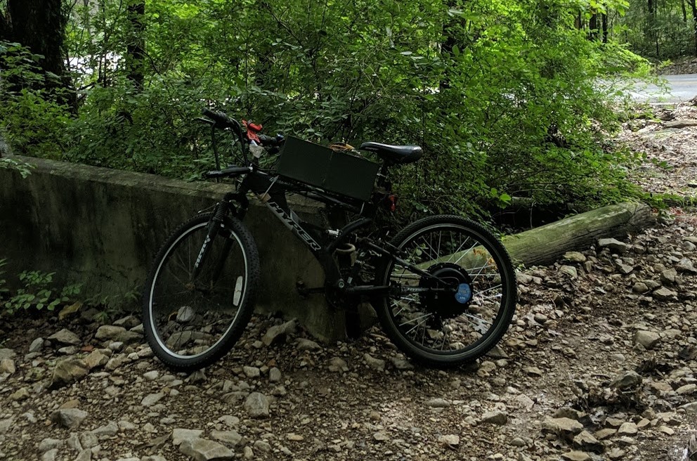
Flashback to August of 2020, my best friend and roommate came back from a state hours away with an E-bike battery he made following this video. He didn’t have a bike at the time but eventually I found a good candidate for him at a thrift store for $15 and he was able to use it for his conversion. Riding his bike immediately convinced me I needed to convert my own, but it left me wondering where to start.
Free Body Diagram
Like with all other things in life the best place to start is with a free body diagram. There are 4 primary forces acting on a bicycle:
- Rolling Resistance
- Aerodynamic Drag
- Gravity
- Propulsion (force at the driven wheel moving you forwards)

Now to characterize these forces here are all of the symbols we will be using:
| Constants |
| ρ : Density of the atmosphere |
| A : Frontal area of the bike and rider |
| W : Weight of the bike and rider |
| crr : Coefficient of rolling resistance |
| CD : Coefficient of aerodynamic drag |
| Variables |
| θ : Angle relative to horizontal travel |
| v: Velocity of the bike relative to the air. |
Aerodynamic Drag is calculated using coefficients and frontal areas from here. Using this relationship:

*For all equations in this paper the units should be consistent for the calculations to have meaningful results.
Rolling Resistance is found using a coefficient of rolling resistance from this website and the normal force on the tire in this equation.

Weight is simply the weight of the bicycle and rider with any equipment.
Propulsion: Since the forces sum to zero in the y axis we are left with this simple equation for the propulsive force assuming that the bike is not accelerating along the x axis.

And if we assume that the ground and air speeds are the same we get this equation for mechanical power required to maintain velocity.

Using those relationships I calculated the power required with varying slopes and travel speeds to create this nice graph in excel, assuming an *80% electric drive train efficiency.
*In reality the motor efficiency is far from constant and it changes dramatically with load conditions and speed as seen here. Fortunately, for a hub motor at top speed for fairly level ground it tends to be a lower efficiency bound.

I decided that ~32 mph on flat ground was scary enough on a Walmart bicycle so I settled on a 1500w hub motor pretty early on. Eventually though I switched out the speed controller with this in order to get more customization and smoother starts from a dead stop.
I’m leaving this post here for now, check back later for the final product!

